
Originally from ticket #175.
First of all. I love this. Stick. I need help putting the actual joystick back together. I took it apart to tighten up the spring. But cannot remember how to get it back together. Please help me. So i can get back to playing Third Strike.
Jonathan
Jonathan,
I've attached five photos.
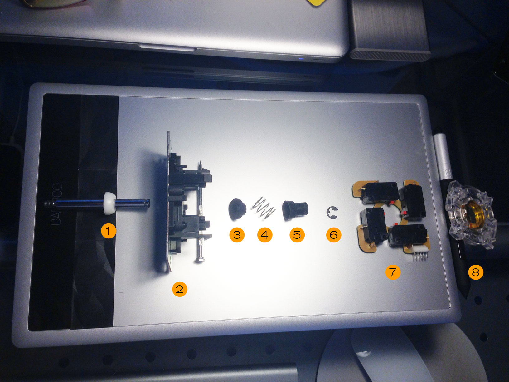
The first photo is a layout of each part of the Sanwa joystick, numbered in order of install and part name:
1. JLF-P-4 Pivot Cylinder
2. Sanwa JLF P-2 Main Body
3. Sanwa JLF-P-6 Pressure Spring Base
4. Sanwa JLF Replacement Spring
5. Sanwa JLF P-5 Actuator
6. Sanwa JLF-E Clip
7. Sanwa TP-MA PCB Assembly
8. Sanwa GT-8F 4/8-Way Restrictor Plate (mine is a Sanwa GT Y Octagonal Restrictor Gate)
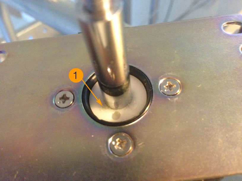
The second photo shows how part #1 - the pivot cylinder - is placed into part #2, the main body. First, attach the pivot cylinder to the joystick shaft as it appears in IMG409a.jpg. Next, place the shaft and pivot cylinder into the joystick body as shown in IMG_407a.jpg
The pivot cylinder controls how the joystick pivots in the body. You'll notice that there is grease on the bottom and in the joystick body. Do not remove the grease. You need it for the pivot to move smoothly.
The third photo shows how the main pieces are put together in order of install.
First, install the JLF-P-6 Pressure Spring Base (#3) into the JLF body. There will be some grease at the shorter end of the base, indicating that it makes contact with the pivot cylinder. Note that the longer end of the base points outwards from the body.
Next, put your spring (#4) onto the spring base. Once installed, place the actuator (#5) atop the spring and spring base.

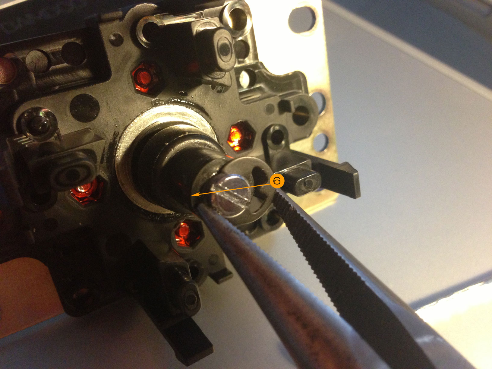
You're halfway done. The tricky part is putting the e-clip (#6) back onto the shaft. The e-clip holds everything (spring base, spring and actuator) on the shaft together. Because the spring puts pressure on the actuator, it's a bit difficult to put the e-slip back on. The best method I've used is to push down on the actuator with your thumb, and then loosely attach the e-clip to the side of the shaft. You'll notice that there is a groove on the shaft to accept the e-clip. Once done, depress the actuator and spring so that it forces the e-clip to stay in place.
If you look at the fourth photo, you'll see that I used needle-nose pliers to push the e-clip back onto the shaft.
Finally, as depicted in the fifth photo, place the TP-MA PCB Assembly (#7) onto the joystick body, and then push the GT-8F 4/8-Way Restrictor Plate (#8) onto the body. For the TPMA, position it so that you can easily install the 5-pin harness. The 5-pins from the TPMA control direction, so you won't have to worry about how the TPMA is oriented. The GT-8F 4/8-Way Restrictor Plate fits onto the joystick body's four plastic extrusions. The gate can only be installed one way, so if you find it doesn't fit when you try to push down, simply flip it over. You want the smooth, flat part of the gate to rest against the TPMA, and the rough part to stick out.

This should help when I attempt to install extended shafts into my JLFs... at least that's what I'm hoping!